It was apparently too simplistic to remove the base from our design, so let’s re-introduce it in the figure below.
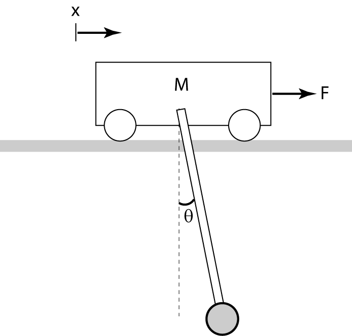
We are now interested in designing a controller which dampens out the oscillations of the pendulum while forcing the base to come to a rest close to the initial position.
Control structure
If we should follow the philosophy from the earlier in the tutorial, the way to deal with the base would be to derive a differential equation describing how the applied motor torque influence the angle of the pendulum and the position of the base, and then design a controller that control the dynamics of both. We will not use this approach in this project for two reasons: first, it is quite complicated to develop such a model, and secondly, even if the model is given it would require more than high school math to analyze and understand how to control. To keep things simple, we are going to use the control structure shown in the figure below.
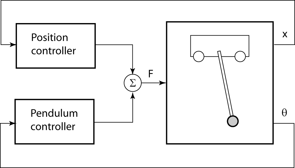
The basic idea is to keep the pendulum controller fixed and design an additional controller that controls the position of the base while accounting for the fact that the pendulum controller is now running (thus altering the system dynamics).
If the balancing controller would work perfectly, one could imagine to disregarding the pendulum completely while modelling the brick position. Newton’s law  , would result in a model on the form
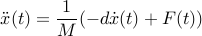
where  is the friction force. We could then design a controller for this dynamics using the same approach that we used for the pendulum. We are going to do something even more simple: we will simply propose a control structure, and tune the controller parameters by trial-and-error.
The specific control structure we will use is called PID control (for proportional-integral-derivative control) and takes the form
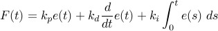
where the control error  is the error between the desired and actual position. Compared to the PD controller that we discovered earlier in the tutorial, this controller has an extra term proportional to the integral of the error. It turns out that this “integral action” is very useful for eliminating errors due to stationary disturbances, and to make the controller less sensitivt to differences between the model and the dynamics of the actual system. Despite its simplicity, the PID controller is still the dominant control structure in industry. Let’s see how we can implement it in our LEGO Mindstorm kits.
Measuring the position of the brick
To control the position of the base, we need to be able to measure it. As discussed earlier, we will use the digital encoders on the motors to measure the position. The NXC command for doing so is
motorPos=MotorTachoCount(outPort)
Since we are having two motors and we are moving on a straight line, we will use the average readings from the two motors as position estimate.
int motorPos=0;
...
motorPos=(MotorTachoCount(OUT_A)+MotorTachoCount(OUT_C))/2;
Implementing the PID controller
To evaluate the PID control law
we needs to compute the control error, its derivative and maintain an estimate of the error integral. Using the approximations
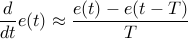
and
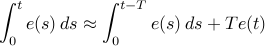
We can see that we need to remember the error  and its integral
 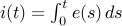 between sampling instants. This leads to the following PID controller code segment
#define REFPOS 0
#define PERIOD 10
#define KP 1
#define KI 1
#define KD 1
...

int x;
int error;
int errorPrev=0;
int errorIntegral=0;
int errorDerivative=0;
int control=0;
...


x=(MotorTachoCount(OUT_A)+MotorTachoCount(OUT_C))/2;

error=REFPOS-x;
errorIntegral=errorIntegral+error*PERIOD/1000
errorDerivative=(error-errorPrev)*1000/PERIOD;
control=KP*error+KI*errorIntegral+KD*errorDerivative;
errorPrev=error;
You will then need to combine the control action suggested by the position controller with the one computed by the balancing controller before adjusting the total power to be in range and commanding it to the motors. You will see how we did all this in the code segment below.
Resulting robot and program
The complete code for the controller which combines the pendulum and position control can be found here. If you understand everything so far, then you are very well set for the Segway Challenge! Good luck!