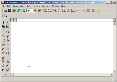
Fig-4: Directory setup
Create a project library using the menu File->New->Project
Select this project and create a schematic using the menu File->New->Schematic
When creating the schematic an empty schematic window opens (Fig. 4)
Fig-4: Directory setup
The new schematic is still untitled. Use the Save as function to save the schematic using the name you want.
Select the Edit->Add menu to add components, or use the button (Fig. 5).

Fig-5: Add component
This brings up the library browser (Fig. 6).
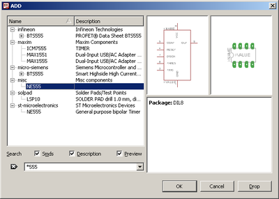
Fig-6: Component library browser. Search for components using the filter option. To view all libraries, clear the search field.
Select the 555 timing circuit from the
misc/NE555 library
You can easily find components using the search field.
Various resistors and capacitors can be found in the rlc library. Use 0603 resistor footprint using the R-EU_ footprint for European symbols.
rlc/R-EU_/R0603
and capacitor using the 3216 package:
rlc/CPOL-EUA/3216-18W
Place the components in the schematic. When placing the components you can rotate the symbol using the right mouse button.
To mirror the component, place the component in the schematic, select the mirror function (Fig. 7) and click the component you want to mirror.

Fig-7: Mirror component
Set value of the component using the Value function (Fig. 8). By default the name of the component is assigned automatically (R1, R2 etc.). If you want you can also specify the name of the component. Remember that two components can not have the same name, this will create an error message.

Fig-8: Set component value
For the GND connections use
supply1/GND
This generates a global net named GND. All components connected to this net are connected even when there are no visible wire in the schematic.
Finally add a connector to be able to connect the power cable. Use for example the
con-molex/22-23-2021
two pin connector.
If you want to change the package at a later stage you can do this using the Edit->Change menu and select the Package option.
You can move components using the Edit->Move menu, and selecting the component you want to move.
Use the side scrollbars or the mouse wheel and button to pan and zoom in the window.
A convenient way to move around the window is to zoom out using the wheel, and then zoom in on the area you are interested in.
To fit the whole schematic in the window, press the zoom-fit button (Fig. 9).

Fig-9: Fit schematic in window
When you have placed the components in the schematic you need to connect them using wires. Add wires using the Draw->Wire menu, or by using the add wire button (Fig. 10).

Fig-10: Add wire
Be careful when adding wires, they need to connect to the very pin of the components.
Add the junctions to connect the different wires using Draw->Junction menu.
The final schematic should look like Fig. 1.
Tip: one method to check if all wires are correctly connected to the component is to move the component. If the wires follows when moving they are correctly connected. If not moving they will be connected is the component is placed in the original position.