Denna tjänst avvecklas 2026-01-19. Läs mer här (länk)
IS2500 LabsDenna tjänst avvecklas 2026-01-19. Läs mer här (länk)
IS2500 RFID Systems Laboratories, 2022:
Welcome to the labs for RFID Systems for 2022! In the
first weeks, you will be building your own equipment and tools
that
you can use in later labs and projects. In this first week, we will start to design and
build one of the most important components of any RFID system, which is
the antenna. We will discover in the course that RFID antennas
have a lot to do with the success of any RFID system. In fact,
being very creative with RFID antennas can result in very interesting
new IT products. For example, could you build an efficient
antenna into a wrist watch? How about a winter coat?
Believe it or not, future clothing will probably have several
antennas built into them. You might be wearing some clothes right
now that actually do! This week and next week you will design and
build your
first RFID antenna system.
For other projects, you can find the design rules for making PC boards that we can make in the Mentorspace here.
Project Teams:
In all the labs and for the final course projects
you will be working in project teams of 2 or 3 people at most.
You can form the teams yourselves. Here are some guidelines
to help you do that. What you would like to have is a team that
will give you the greatest chance to imagine, invent and succeed in
performing the RFID project course. Working with people you know
and like helps, but it may not produce the best results. What you
really want in your team are people with very different backgrounds.
This allows you to have lots of different ideas for solving problems
and all necessary skills that your team might need. In the real
world of science and
engineering, ideal teams have people in them with diverse talents.
If you are a hardware
person, be sure the team you are in has skills you don't have, such as
programming or business knowledge. If you
are a
good programmer, be sure the team you are in has someone in who is
a good
circuit designer or has someone who understands people. Do you
have marketing or business skills?
Then you will be an asset on any team in order to come up with an
project that could really have business potential.
With the exception of parts of the final project
report, in this class you will always write your own homework and lab
reports. However, that does not mean that to build your systems
and collect your system data that you will work alone. The actual
lab and project work should be a shared effort of the entire team, and
all team members should be able to transfer some of their own knowledge
to the other members of the team. In other words, teach each other what
you know! For example, if you are a
hardware person now is your chance to acquire skills in embedded or
system level programming and maybe marketing. If you are a
software person, now you can learn some hardware design and
construction skills along with some business skills. If you are a
business oriented person, you can now be exposed to many of the
technical aspects of IT product design that have impact on product
related business decisions. Teams that help and learn
from each other generally achieve the highest level of success in real
engineering jobs. I have noticed that this is also true to have
success in the course. So, when you form your team keep this in
mind.
Week 35:
RFID Engineering Requirement:
For this week's lab, imagine you are working for a
company
that makes and sells RFID systems. Your marketing department has
come in with a customer request from a large shopping center in the
Stockholm area. They are working with the stores in the shopping
center to put RFID tags into product packaging and smart shopping bags
to do the following applications:
- Help keep track of store inventory at all their stores.
- Make buying and paying for store items easier and more accurate.
- Allow customers to access more information about a store item.
- Collect data about what their customers are shopping for and how they shop.
The shopping center has contacted your company because they want
to buy intelligent sales kiosks for their stores that can read
the
RFID tag in the product packaging and smart shopping bags when they are placed down on its surface.
After doing a study, you have found that the different stores
could have
several
different sizes of kiosks, and no single RFID design is the obvious
right choice. However, you have determined for now that any kiosk
design only has to be able to read packages and bags when they are
actually placed onto it, so a short range inductive RFID solution
using a
reader frequency of 13.56 Mhz would probably be best. You will
start to design your system for that.
Each RFID design team will be assigned one possible kiosk surface size for a RFID antenna design.
In the lab you will find the following equipment and supplies to help you do this:
1. The dimensions of the kiosk surface you need to design an antenna for.
2. A quantity of solid copper wire, tape and cardboard.
3. In addition to the usual lab equipment, there is also a special
meter that can measure inductance and capacitance. It is called
an LCR meter.
The goal of the lab is to start the design of a RFID loop antenna that
can be used to read the RFID tags in the packaging and smart bags, and that
fits the specified sales counter surface. Recommended steps are the
following:
1. Download a copy of the HF Antenna Design Notes
from Texas Instruments. This is a very useful and interesting document. For right now be sure to read sections 5, 6.1
and 6.2 although eventually you will want to read the entire document.
2. Design the shape of your RFID loop antenna. You can make any
shape that makes sense for the sales counter you are designing for.
Although the Design Notes talk about making the antenna out of copper
tube, we will use solid copper wire instead. The antenna will
work just as well. The reason for using copper tube is because it is
rigid and self supporting so you can pick up the antenna and it won't
lose its shape. You will accomplish the same thing if you build
your antenna by taping the copper wire to a piece of
cardboard. That way you can pick up your antenna and move it
easily without changing its shape.
3. After designing the shape of your antenna, build it by bending the copper wire
and taping it to the cardboard. Leave about a 1cm gap where the
ends of the wire come together. Hint: It is a good idea to remove any plastic insulation on the wire
you use for the loop antenna, as it will make things easier in later
steps.
At this point, the antenna is not finished yet. In order to continue the antenna design you need to
characterize the loop of wire you have taped onto your cardboard.
To do that you will need to perform the following.
4. Using equation 2 on page 11 of the HF Antenna Design Notes, compute
the inductance of your wire loop. If your wire loop is round or some other shape
instead of rectangular, you can still use equation 2 by imagining that
your antenna is square, and coming up with an estimate for the length of
the sides of an equivalent square.
5. Next, use the LCR meter in the lab and measure the actual inductance
of your loop of wire. Do this by soldering lengths of wire to the
points on your wire loop where the ends of the loop come close
together. One thing to ask yourself is how long should the
lengths of wire be that connect your wire loop to the LCR meter.
Does it matter? To find out, do two measurements. The
first measurement should be with wires about half a meter long.
The second measurement should be made with wires as short as you
can make them and still connect the loop to the LCR meter, Record
in your notes how long those short wires are. Also record both
values of inductance you measure.
6. Taking good inductance measurements isn't always easy.
With the short wires connecting your wire loop to the LCR meter,
touch the wire loop with your hands while you are measuring the
inductance. Record in your notes the value you see.
7. While you have your wire loop connected to the LCR meter, push the
button labeled 'Q' and write down in your notes the value you see.
You will need it for the lab next week, and we will talk more
about what 'Q' is then.
8. The wire loop will be used to make an RFID antenna by forming
a parallel resonant circuit with a capacitor. Compute the value
of the capacitor needed to form a resonant circuit with your wire loop
at a frequency of 13.56 Mhz. Be sure to show the calculations or method you used to determine the capacitor value.
To complete this week's lab, hand in
the following anytime before Friday, September 9. Note that for this lab,
everyone needs to individually hand in their own report. Hand
it in by emailing it to me. You can send it to me as an
email attachment in PDF, Microsoft Word (doc or docx), or as a LibreOffice
Writer document (.odt my favorite!). You should avoid other
formats as I may not be able to open and read them. Be sure to
put your name on your report, and give the report a file name that says
what it is, for example your_name_IS2500_week35_project.pdf.
Something like that. Your report should include the
following:
A. A drawing of your wire loop antenna. Indicate on the drawing
the dimensions of the wire loop. Instead of a drawing, you can
take a photograph of your wire loop and include with that indicated
dimensions instead.
B. Show the calculation performed in step 4 above.
C. Present the data you collected in step 5 above. Explain why
you think the inductance measurements are different for the two
different lengths of wire that connect your wire loop to the LCR meter.
D. Discuss what you saw when you touched the wire loop with your hands
in step 6. Explain why you think you got the data you did in
this step.
E. What is the value of the capacitor computed in step 8. Also
compute and show what the values of capacitive reactance for your
chosen capacitor and inductive reactance for your wire loop will be at
13.56 Mhz.
To get
ready for the next lab, be sure to read the rest of the HF Antenna
Design Notes. We will discuss it all further, so don't worry at
this point if it doesn't all make sense. We also have
an antenna analyzer similar to the one discussed in section 2.2 of the
HF Antenna Design Notes and next in week's lab we will use it. We
also have a device called a Network Analyzer which can show even more
data than the antenna analyzer. Both analyzers are very cool!
Week 36:
This week is a continuation of the lab from last
week.
Your goal this week is to finish the RFID antenna you started,
and verify its operation by using it to read a tag. To
do this you will need to use a computer, so be sure one of the members
of
your group brings their laptop to the lab. It can be running just
about any operating system, so Windows, OSX, or Linux is fine.
You will also need the
wire loop that
you built and characterized last week. Before starting this lab,
be sure you have completely read the Texas Instruments Document HF Antenna Design Notes.
Also as part of this lab you will use some RFID readers with
your antenna design to show that your antenna works and can be used to
read RFID tags. In order to use the reader you will connect it to
the laptop computer that one of your partners has brought to the lab.
To talk to the RFID reader the laptop needs to have Python
version 3 running on it. You also will need to have the pyserial
module for Python version 3 installed on your
laptop. There are two versions of the python code that talks to
the RFID reader. One is GUI based, and the other just uses the
command line in a console window. If you want to use the GUI
versions of the python code for the RFID reader then you also need to
install the python tkinter module. Depending on your operating
system, you may also need to install Tcl/Tk, which is separate from
python, but is used by tkinter. TCL stands for Tool Command
Language, and is very useful if you are a person who likes to collect
data and control things with your computer. Very cool! To
see if you have tkinter and Tcl/Tk installed correctly on your system,
run the command:
python3 -m tkinter
If
all is well, an example window will appear with a couple of buttons and
information about what version of Tcl/Tk you have.  If you decide
you want to just use the command line version of the python code, then
you don't need to worry about tkinter or Tcl/Tk, but you will need to
figure out what in your computer the RFID reader is connected to, such
as something like /dev/ttyUSB0 (linux), or COM8 (windows).


     The actual python code that can talk to the
RFID reader is on a memory box in the Mentorspace.  Plug it into a
USB port on your computer and copy the files.
Also, you may need a device driver to talk to the
RFID boxes. The RFID box uses a USB device that provides a
"Virtual COM Port" for use by your laptop. Most modern operating
systems have the drivers for this device already installed or are able
to find and install the drivers when the RFID box is plugged in.
If not you may have to install the driver manually yourself.
If you need to do that then drivers for most all current operating systems plus full installation instructions can be found here.
To complete your RFID antenna, do the following:
1. If you did not measure the Quality Factor (Q) of your antenna last
week, do it now by connecting your wire loop to the LCR meter. Push the
button labeled 'Q' and write down in your notes the value you see.
2. The Q of your antenna will determine how much bandwidth it is useful
over. The value of Q measured by the LCR meter for your wire loop
is the value at a frequency of 1 Khz. You need to know what the Q
is at 13.56 Mhz which is the frequency the RFID reader uses. To
get a usable value of Q at 13.56 Mhz, just multiply the value of Q you
measured with the LCR meter by 13560 and write this down in your notes.
The value 13560 is just 13.56 Mhz divided by 1 Khz.
3. For your antenna to have a
sufficiently wide
bandwidth to read a RFID tag the Q of your antenna should only be about
20 at 13.56 Mhz. The value of Q you calculated in the last step
is probably a lot higher than that. (If it isn't, check your math or
re-measure your wire loop!) To lower the Q, you will need to use
a
'Swamping Resistor'. This is described in section 6.3 of the HF
Antenna Design Notes. Perform the necessary calculations to
determine the correct value of your swamping resistor by solving
equation 6 on page 14 of the HF
Antenna Design Notes. On page 13 where it says to " assume a
value for the present Q", do NOT use the value "50" as they suggest.
Instead, use your actual measured and scaled value of Q that you
recorded in the last step.
3. Next, you need to decide on a method to match your antenna to the
RFID reader. The RFID reader expects to see an antenna with a
characteristic impedance of about 50+j0 ohms. Read over chapter 7
in the HF Antenna Design Notes and decide what sort of matching network
you would prefer to use. The materials we have in the lab are
best suited to either a T-match as shown in figures 16, 17 and 18, or a
Gamma match as shown in figures 12, 13 and 14. For either the T
or Gamma match, you can use copper wire to make the connections to your
wire loop, you
don't need copper tube. Where the T or Gamma match attaches to
your wire loop, a good idea would be to use alligator clips so that you
can move the connection point easily. You will need to do this
when you tune your antenna.
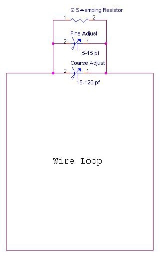
4. Now, assemble your antenna. First, attach your capacitors and
swamping resistor to the open ends of your wire antenna in a similar
way that figure 19 shows in the HF Antenna Design Notes. To make
it easy to adjust your antenna, you should use two variable capacitors
instead of one variable and one fixed capacitor as shown in figure 19.
The circuit arrangement of the two variable capacitors and your
swamping resistor are as shown below. Note that one variable is a
'coarse adjustment' and has a range of about 10 to 120 pf. The
other variable capacitor is for 'fine adjustment', and has a range of
about 5 to 15 pf. Also, your swamping resistor can be just a
normal resistor from the parts bin in the lab. You don't need a
high power thick film resistor as shown in the Design Notes because
your RFID reader can only radiate a maximum of 0.125 watts. That
isn't much, so the swamping resistor does not need to be able to
dissipate a lot of power. You may not find the exact value of
resistance you need in the parts bin so
choose the closest value you can find. It does not have to be exact.
5. The next thing to do is to attached a piece of RG-58 coax cable to
your antenna. To be sure that we have enough RG-58 coax for all
the lab groups, your piece of RG-58 coax should be not much longer than
about 80 cm long. There is a handy length guide on one of the
tables in the hardware lab. One end of the coax cable connects to
your antenna
though the matching network you have chosen, either a T or Gamma match.
The other end needs to be attached to a PL-259 connector so that
it can be connected to the RFID reader. The PL-259s are very easy to connect to the coax cable. See
the instructions here.
6. When your antenna is completely built, the next task is to tune it so
that it has a characteristic impedance as close to 50+j0 as possible.
To do that, use the MFJ antenna analyzer we have in the hardware
lab. Don't move the analyzer out of the hardware lab, but use it only in
the hardware lab. The basic steps are as follows:
- Connect your antenna to the antenna analyzer. Note that ONLY antennas should ever be connected to the antenna analyzer.
- Turn the antenna analyzer on by pressing the red button.
The analyzer will do some self checks and eventually show a
display that looks like :
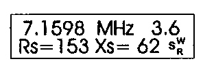
- Be sure the FREQUENCY knob is set to the 10-27 Mhz setting.
Then, adjust the TUNE knob so that the indicated frequency is as
close to 13.56 Mhz as you can get it.
- Now, adjust the variable capacitors on your antenna so that the
value for Xs on the analyzer is as low as you can get it. Ideally
it should be 0, but if you can get it less than or equal to 5, that is
pretty good.
- Next alternately adjust the position of your T-match or Gamma
match to get the value for Rs on the analyzer to read 50 ohms.
You will need to adjust both the position of your T or Gamma
match, and readjust the capacitors in order to do this. If you
used alligator clips as mentioned in step 3 then adjusting the position
of your T or Gamma match will be easy. Adjust the match position
and capacitors iteratively until you get a reading on the antenna
analyzer as close as possible to Rs=50 ohms and Xs = 0 ohms. At
this point your antenna is matched.
- Turn the antenna analyzer off and disconnect your antenna from the analyzer.
7. Now, if you have not already done so, disconnect your
antenna
from the antenna analyzer and connect
it to one of the RFID readers attached to your laptop computer.
Then, using either the python program s6350_reader_version.py
(command line version) or s6350_reader_version_tcl.py (GUI version), run
it
to ask the reader for its version information. For example, if
you want to run the command line version, and the reader is connected
to COM8 on your windows laptop, you can run the program with the
command:
python3 s6350_reader_version.py COM8
If you want to run the GUI version, you can say
python3 s6350_reader_version_tcl.py
Or you can just find the program's icon and click on it. If all is well,
the program
will start and tell you the firmware revision of the RFID reader you
have. It should look something like this:
Reader Version
Version : 01.46
Type : Firmware
If you don't see this, check that your RFID reader is plugged into the
provided power supply and check your communication settings. The
communication settings necessary to talk to the RFID reader are:
- Use the same COM port number that your USB VCP driver is using.
You may have to use the Hardware Manager in Windows to see
what that is.
- 57600 baud (if 57600 baud doesn't work, try 9600 baud instead)
- 8 data bits, 1 stop bit
- no parity
- no flow control
After you see the correct reader version indicated as
described in step 7, you are ready to try reading a tag. The tags we are using are ISO15693 protocol tags.
9: Choose a tag out of the box in the lab. The tag
itself in inside a paper holder, and the holder has one of the letters
A, B, C or D written on it. Put the tag you want to read near your
antenna.
Choose the python program called s6350_iso_transponder_details.py
(command line version) or s6350_iso_transponder_details_tcl.py (GUI
version) to read the
Transponder ID of the tag. Note that you should not use
the reader utility that turns the RF carrier ON or OFF. The
carrier will turn on automatically when you try to read the tag, and
will turn of again when the reader thinks it is done. You will
know when you are
reading
your RFID tag when you see an output that looks something like the
following:
Transponder ID: 0xXXXXXXXXXXXXXXXX
DSFID: 0xXX
If you don't see something like the message above, then suspect there
is something wrong with your antenna feeders, or that the antenna still
isn't matched, or try moving the RFID tag to another spot on or near
the antenna. When you see the tag information write it down and then put the tag back into the box in the lab after you
are done using it, as we will want to use them again later.
To complete this week's lab, hand in
the following by the end of the day on Friday, September 16.
Note that everyone needs to individually hand in their
own report. Hand
it in by emailing it to me. You can send it to me as an
email attachment in PDF, Microsoft Word (doc or docx), or as a LibreOffice
Writer document (.odt my favorite!). You should avoid other
formats as I may not be able to open and read them. Be sure to
put your name on your report, and give the report a file name that says
what it is, for example your_name_IS2500_week36_project.pdf.
A. What is the Quality Factor (Q) value that you calculated for your
antenna system? What value of swamping resistor is necessary to
obtain an overall Q of 20? Show your calculations.
B. In the lab you will find some clear plastic bags, a silver metalized
bag and some aluminum foil. After you get your antenna system
working and can read the RFID tag, place your tag into a clear plastic
bag and try to read it again. Record if you can still read it as
easily as you can read the tag alone. Repeat the experiment for
the silver metalized plastic bag. Finally, put your tag inside a
single layer of aluminum foil and do the experiment one more time.
For each of these 3 situations, is the ability of your system to
read a tag changed at all?
For this question, say whether you see any difference in the
ability to read a tag, and suggest why you see the results you do.
In your explanation for what you see, try to be as analytical in
your explanation. In other words, try to base your explanation on
physical properties of the system.
C. Draw the final schematic of your antenna. Be sure to show what kind of matching network you used.
D. What is the Transponder ID code for the tag your group used?
Be sure to mention the letter (A, B, C or D) that was written on
the paper tag holder.
Week 37:
The next thing needed for your RFID system is to
characterize its performance. All of the tasks to do this week
have to do with measuring how well tags can be read by your antenna and
reader system with respect to orientation and distance. Once
again during this lab you will need to refer to the Texas Instruments
Document HF Antenna Design Notes.
1. Your customer, the shopping center in Stockholm, has specified a system that can be solved using an inductively
coupled RFID approach. Even though it is inductively coupled, the
antenna you built has directional properties. In order to provide
documentation to the shopping center about the RFID system you have designed for
them, you need to completely characterize the electromagnetic field
pattern that your antenna produces. In other words, where is the
field strong, and where is it weak? This information will help
when your antenna is installed in kiosks in the food
stores. To make the field strength measurements necessary to
determine the field pattern, you need to build a charge level indicator
specifically for your 13.56 Mhz system. Another name for this is an envelope detector.
In the lab you will find the following materials to
help you do this. Cardboard, insulated wire, and a few
electronic parts. There are also copies of page 4 from the HF Antenna Design Notes. Your task is to build the charge level indicator as shown on that
page. But, there is a major difference. The information on
page 4 suggests that you make your charge level indicator out of an
unwanted RFID tag. You don't have any unwanted RFID tags, so you
are going to build your own tag. Your tag is the receiver part of
a real tag. It has the tag's antenna, resonant circuit
(which includes the antenna), envelope detector and low pass filter.
The circuit is shown also at the top of page 4.
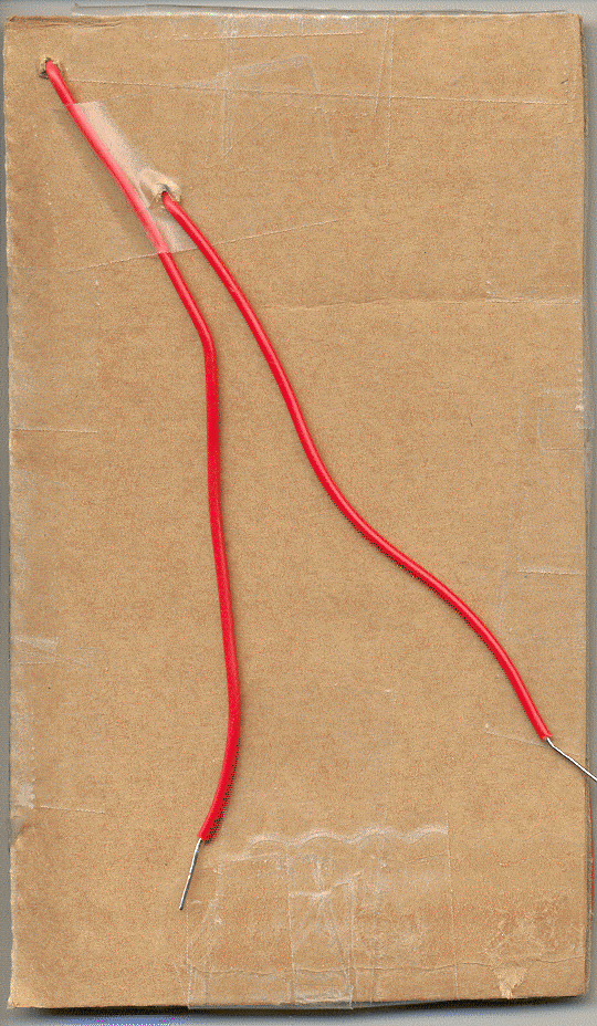
To build the body of your tag, (technically it is called the inlay), do the following:
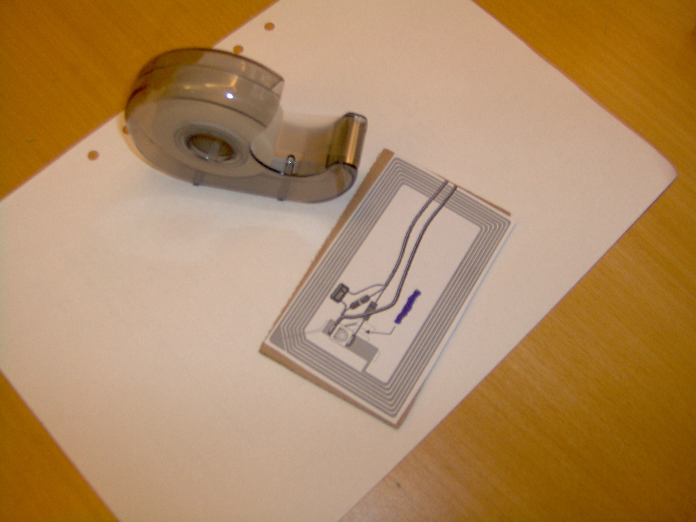
- Cut out the picture of the RFID inlay shown in Figure 3 on your copy of page 4 from from the HF Antenna Design Notes. You will use it as a mechanical template.
- Tape your template to a matching piece of cardboard as shown in
the picture below. You can just see the cardboard under the
template. The cardboard gives mechanical rigidity to your tag and
will make it easy to use.
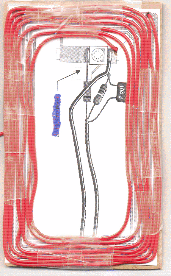
- Next, using the image lines of the flat coil on the template,
wind your coil using the insulated solid core wire. Solid core
wire is used because when you bend it at the corners of your template
it will hold its shape much better than stranded wire. Be sure
your windings are flat and that the turns do not overlap each other.
Use lots of tape to hold your windings onto your inlay. Paper masking
tape is fine; it does not have to be transparent. One suggestion
is to punch holes in your template and route the ends of your coil wire
to the other side of the cardboard. Put as many turns of wire
onto your coil as shown on the template. When you are done, the
front and back of your inlay should look something like this:
 |
 |
When you have finished winding your inlay coil, use the LCR meter in
the lab to measure its inductance.
2. After you have the inductance of your coil, compute the value of
capacitance needed to form a parallel resonant circuit at 13.56 Mhz.
If it is less than 15 pf, then you only need to use the variable
capacitor to form the resonant circuit as shown in the charge
level indicator schematic. You may find you need more than 15
pf. If you need more than 15 pf, but less than 25 pf, then use an
extra 10 pf capacitor in parallel with the variable capacitor. If
you compute that you need more than 25 pf, then something is probably
wrong. Check your inductance measurement, or check your
calculations for inductive and capacitive reactance to find out what is
wrong.
3. Now, assemble the components of the charge level indicator onto the
back of the cardboard. The black stripe on the diode indicates which end is the cathode. The voltmeter shown in the schematic is
one of the voltmeters on the lab bench, so be sure to attach wires to
your inlay so you can connect it to a voltmeter. The voltage it
measures is the output of the detector which is made up of the
diode, 1meg resistor and 100 nf capacitor. Here is a hint.
To make it easy to adjust the circuit, you can pre-adjust the
variable capacitor to the value you calculated you need for resonance
in the previous step. Include the extra 10 pf capacitor if you
need it. Connect the capacitor(s) to the LCR meter, and adjust it
until you get the value you need. Then carefully assemble it into
your circuit.
4. Now use your charge level indicator to measure the
field strength over the entire area of your antenna. To do this,
connect your antenna to a RFID reader, and test that it still can read
a real RFID tag. Remember to keep the antenna away from metal
objects. Then, to measure your field strength, do the following:
- Connect your charge level indicator to a voltmeter. Adjust the voltmeter so that it can read levels of 2 volts or less.
- In the user interface for the software that controls the RFID
reader, command it to turn the transmitter ON. To do this select the reader utility that turns the RF carrier ON
or OFF. Be sure to look at the messages coming back from the Python program to be sure the carrier actually did turn ON
or OFF. If it didn't do what you want, just run it again.
- Place your charge level indicator near your antenna. You
should see a voltage. Make the voltage as high as possible by
adjusting the variable capacitor on your charge level
indicator. If you pre-set it in step 3 above, then you should not
have to
adjust it much, if at all. When the voltmeter indicates more than 2
volts, then adjust the voltmeter to a higher measurement range.
When it is clear that your charge level indicator is working, use it to
map out the relative field strength over the entire area of your
antenna. Do this by selecting 16 evenly spaced points over the area defined by your antenna wire loop,
and write down the measured relative field strength with the charge
level indicator about 2 mm
away from the antenna surface. In other words, with the charge level
indicator almost touching the antenna surface. Next, do this
again for distances of 10 cm, 20 cm and 40 cm away from the antenna
surface. You don't need to measure
anything below the loop as that is hard to access, and would face
toward the floor where you probably won't have tags anyway. You might
want to mark where you made these measurements on the cardboard your
loop antenna is attached to as it will be a handy reference. Do the
entire
experiment several times where in half of the experiments the charge
level indicator is held
horizontally, in the other half of the experiments the charge level
indicator held vertically. This allows you to express the
precision, or variance with which you can make these measurements.
After you have made your measurements, be sure to turn the RF OFF!
To do this select the reader utility that turns the RF carrier ON
or OFF. Be sure to look at the messages coming back from
the Python program to be sure the carrier actually did turn ON
or OFF. If it didn't do what you want, just run it again.
5. Real tags can be read with your antenna over most of its area,
but how much of it? Do you have complete read coverage, or are
there holes? Also, how far away from your antenna can you
successfully read a tag? To answer these questions, go back to
the points on your wire loop antenna that you measured with your charge
level indicator and see if you can successfully read your RFID tag's ID
number like you did last week. Record at what distances away from
the wire antenna loop your can read the ID, and where it fails.
Do this for all of the places you measured in step 4. Like in
step 4, you don't need to do this below the wire loop.
Do this experiment at several times, one set with the RFID tag
held
horizontally, and the other set with the RFID tag held vertically.
Doing the experiment several times allows you to understand the
variability with which the tags can be successfully read.
6. Don't throw away your charge level indicator. You may
want to use it in your projects. Note that although we have been
calling it a "charge level indicator", it is more than that. It
is also a circuit that shows how you can harvest useful power from an
inductive RFID system running at 13.56 Mhz.
To complete this week's lab, hand in
the following by the end of the day on Friday, September 23, 2022.
Note that everyone needs to individually hand in their
own report by emailing it to me. Be sure your report is in either PDF, DOC, DOCX or ODT format, and be sure your name is on it.
A. What is the value of
inductance you measured for your inlay? What is the value of
capacitance you calculated so that the inlay antenna circuit would be
resonant at 13.56 Mhz? Show your calculations.
B. Draw a map of the field strength around and above your antenna at your 16 selected points. Indicate
the relative
field strengths by normalizing the strongest measurement
to 1, and showing values on the map that range from 0 to 1. Show
maps for measurements taken when the charge level indicator was
oriented horizontally and vertically to the antenna. Your maps
should include measurements taken at all of the heights above the 16
selected points and should also show measurement variation. You
don't
need to show anything for below the wire loop.
C. Draw another map showing at what points you can read a
tag, and where you can not read the tag, in other words where the read holes are. You don't need to show
anything for below or outside the edges of the wire loop.
D. Based on the data you reported in B and C, is there anything you
should tell the shopping center about how to put the smart bags on
the RFID enabled kiosk surface you have designed, or does it make no
difference?
What would
you
tell them?
E. (Problem 'E' is a theory problem. You don't need to build anything to answer it.)
You know that one way to make a radiative RFID system be
able to successfully read tags in any orientation is to use
circularly polarized antennas. To do something similar in an
inductively coupled system we can use multiple antennas arranged as
described in chapter 8 of the HF Antenna Design Notes.
In order to make your system read tags successfully in any
orientation, you are thinking about making a rotating field antenna as
shown in Figure 34 in the HF Antenna Design Notes. As
you are describing this to your manager, your manager looks confused
and asks you why the two antennas oriented at 90 degrees as shown in
figure 34 don't result in terrible interference with each other.
Your manager understands that one is horizontal, and the other is
vertical, but your manager is worried that the energy from the two
antennas will interact in strange ways to produce unpredictable reading
results. How would you describe to your manger the way the
antennas work, and why exactly they will not cause interference with
each other? If necessary, draw pictures or diagrams to help
support your argument.
Week 38:
This week your team needs to define a project that
you will design, build and demonstrate over the rest of the term.
Note that although the project represents a large percentage
of your
grade in the course, more important is that it represents an
opportunity to build something really new and fun, and to discover a
lot
about how RFID systems work and what their practical uses and
limitations are. It could even have very interesting side effects
as
well. Students often get an industry internship in part because
of the project that was done for the RFID systems class. The
point is that the course project is not really just about a grade.
It is about doing something that can show the world that you can
design and implement real technology based on the theory you know.
Here are the logistics of the project. You
will need to work in groups of at most 3 people and at least 2 people.
Every
week each group will present during lab meeting time a short
progress report
detailing the work that was done during the week. Note that all
members of your project group must be present during the lab meetings
when you present your progress, and the format of the presentation will
be as a project update typically used at a company. We will go
over how to do that. Also, we will all act
as industrial contributors during this time, and work to help each
other solve
problems and make forward progress. At
the end of the course your team will present and demonstrate your
complete, working project.
Here is a guide for your team to brainstorm and define a
project idea. Any idea is good as long as it satisfies at
least the following:
- It has to use RFID in some way. It can be inductive or radiative RFID.
- Assume that your group is part of a company, and you are making a
RFID based product. Therefore, the project has to be useful for
something. It has to provide some benefit, service, profit, or
advantage to people or society in some way.
- In addition to the RFID, your project should have other elements
of hardware, and/or software. Networked services could also be a
component of your project.
- It should be something your team can reasonably do in the remaining class time. That means you have only about five weeks.
In addition to the list above, be creative! A good project is
one that uses the characteristics of RFID in an interesting way, for
example use it in some kind of process control, as a sensor or
transducer, or modify a system to add functionality to the RFID system.
You could even think about making your own RFID reader or
tags. A very important thing is to be sure your project does more
than just simply
read a tag and look up something based on the ID or repeats of one of
the labs we have already done. Such a project
is too easy to do and does not really show the advantage of using
RFID in a product or service. One more suggestion is to please
don't just buy or copy something ready-made off the
internet, or try to solve the project by cutting-and-pasting things
from some web site. Arduino based stuff from the internet are
notorious examples of this sort of thing, and taking this approach usually
doesn't turn out very well because you won't understand why things
don't work, and that won't help your presentation, demo, or reports.
It's important that you show that you
understand RFID technology, how you used it in your project, and why
you
got the results you did based on good scientific and engineering
processes.
You can use the Mentorspace anytime you want in order to use the RFID systems or
build parts of your project. For RFID readers and tags, in
addition to the
inductive systems you have been using in the lab, we also have a 915
Mhz passive radiative UHF RFID system, and one 125 Khz low frequency inductive system with very
small tags that can be used.
For this week, your group needs to to do two things. First, prepare a short presentation about the project that your group would like to do. The presentation
should take about 5 minutes, and should have enough information in it
so that at least the application of the RFID system is clear. You
will present your idea during our class discussion time on Wednesday, September 28. Also, as a group you need to write a project proposal document that your group can
use as an initial plan for designing and building your application.
Your project proposal should be about 2 pages long maximum, and
should contain the following information.
- A description of what you are going to design that uses RFID.
- A description of what the value of the system is. Describe
what benefit, service, profit or advantage it will have to people or
society.
- An outline of what tasks your team will need to perform to complete the project, and a time line for each task.
- A list of what resources you will need to complete the project.
- A list of the team members showing who will be assigned to what task. In other words, who will do what.
The purpose of this is for you and I to agree that you idea is OK
for the class and that it can get done in the time we have. If it
isn't then we will discuss changes you can make so that your project
idea
is acceptable.
At this point in time your descriptions will be at a high
level, so although you don't need detailed schematics or lines of code,
you do need block diagrams, pictures, charts, or other visual tools to
make clear what it is you are going to do. If you have group
members who have taken the course in Product Realization Processes or
a course in project management, then they know how to use things like
gant charts, pert charts
and other tools to communicate details of project logistics and
planning.
Use those tools! They will really help you in planning,
reducing uncertainty, and
in keeping the number and complexity of tasks realistic.
Your group should turn in only 1 proposal document that is the shared
work of
your entire team. Your project proposal document is due by the end of the day also on Wednesday,
September 28 by emailing it to me in PDF, DOC, DOCX, or ODT format. Be sure the names of
everyone in your team is written on the document.