A major problem for sUAS (small Unmanned Aerial Systems) is to interact with other aircraft in the airspace. A problem that often is refered to as "See and Avoid". The small size of a hobby-level multirotor makes it difficult to see in time for the pilot of a conventional, full-size aircraft. One simple method to make the drone more visible is to add lights.
Many people add lights to their own liking, mainly to make it easier for the operator to see the attitude of the drone. I, however, decided to go by the book and add proper navigation lights, or position lights, to my F550. But what lights are proper navigation lights and how to mount them?
A commercial airliner has a lot of lights with different usages (se link). However, I'll put only red, green and white navigation lights and orange anti-collision beacons on my drone. The beacons will be implemented as strobes using the 555 timer circuit.
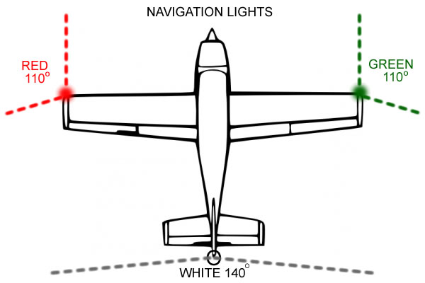
The navigation lights are only supposed to be visible from certain sectors. If you see the green light, you are looking at it from its right. If you see the red light, you are looking at it from its left. If you see the white light, you are looking at it from behind. If you see both the red and the green light, it is pointing directly at you. To achieve proper sectors I'll build screens that doubles as mounts for the LEDs.
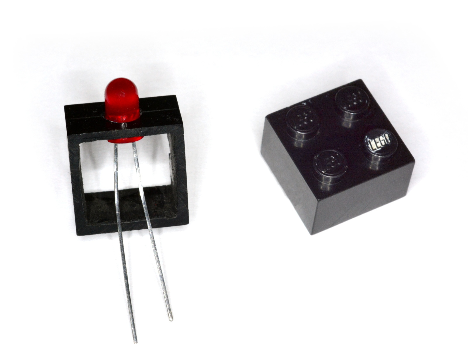
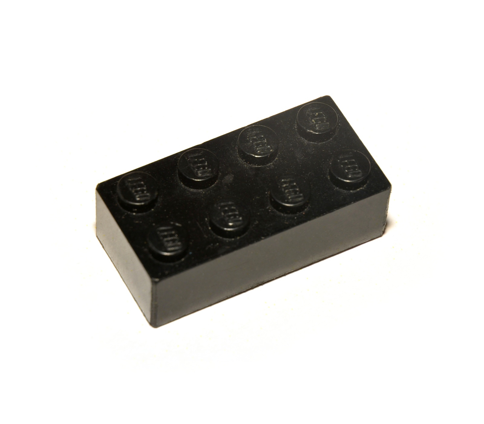 The material needed I need is taken from a piece of LEGO. In this case a black 4x2. LEGO-pieces are cheap and readily available in toystores and on eBay (even more readily available if you have kids). But any piece of plastic with a square corner would do.
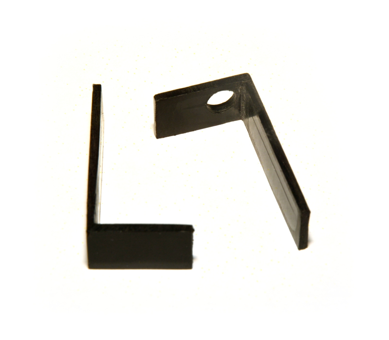 Here I have cut away the top of the LEGO-piece and cut the remaining frame in two so one short and one long side still are together. In one of the pieces I have drilled a 5 mm hole for the LED.
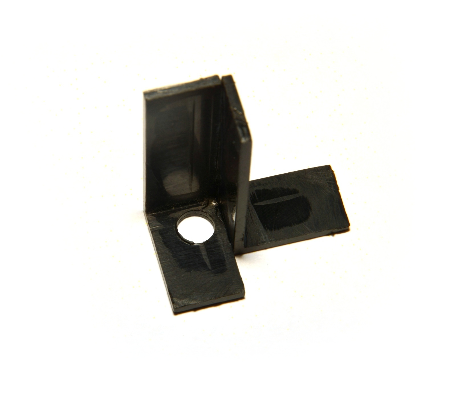 Now the two pieces are glued together with cyanoacrylate. This is the starbord screen. Note that the right piece should be glued to the left side when making the port screen. Otherwise it will be upside-down, facing inwards.
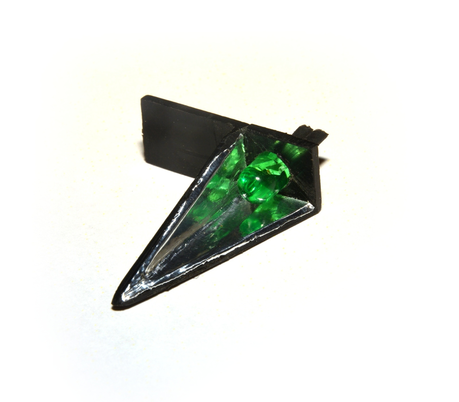 Now the excess parts has been cut of, the inside has been covered with aluminum tape to make it reflective and a dummy LED has been inserted in the hole. The pointed shape of the screen is to form the apropriate sector also in the vertical plane.
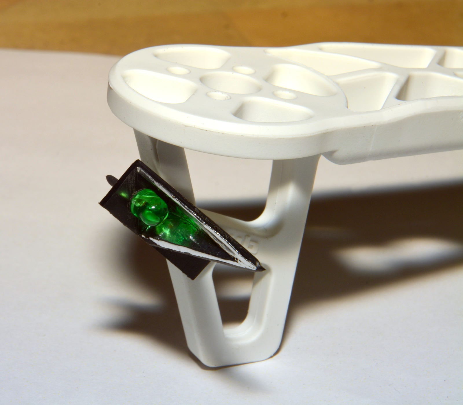 The screen superglued the leg of the right arm. Later it turned out that the plastic in the arm was not so adhesive to superglue, so now it is mounted with a nylon M3 screw instead.
The white arm is only used for testing. The finished multirotor will have black arms, that's why I picked a black LEGO-piece.
The aft screens will look similar, but with a more blunt shape, so a 3x2 LEGO-piece would be sufficient. They will be mounted facing inwards on the aft arms with overlaping sectors.
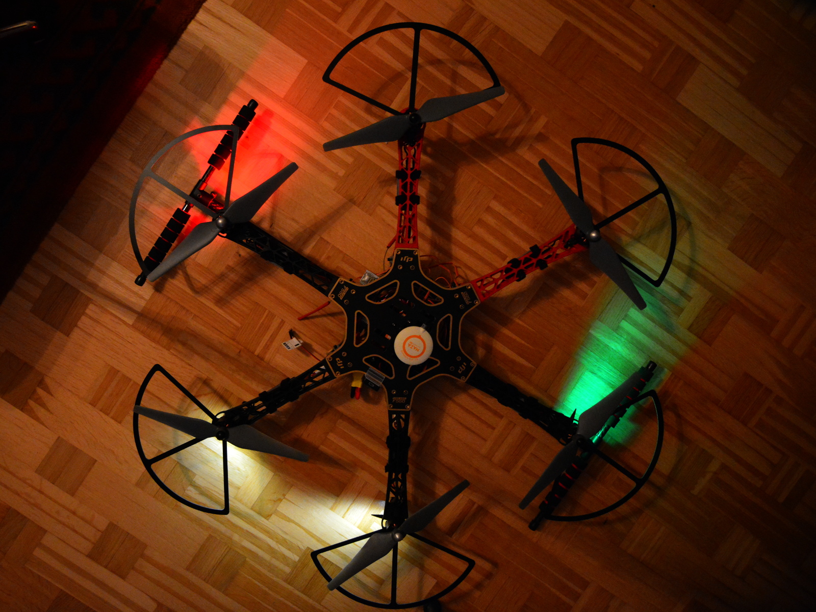 The lights mounted on the assembled frame. The light sectors appears fairly consistent.
 Two anti-colision beacons goes onto this aircraft; One on the top and one on the bottom. The mounts for the beacons are also made from LEGO-pieces. One 2x2 with the top cut off and a 5 mm hole for the LED in one of the sides. The opposite side will be glued to the top or bottom plate of the multirotor.
From the begining I planned to build my own strobe generator using a 555 timer circuit (see diagram). I got it to work just fine on a lab board, but it did not work when solderd to a real PCB. I guess i fried the 555.
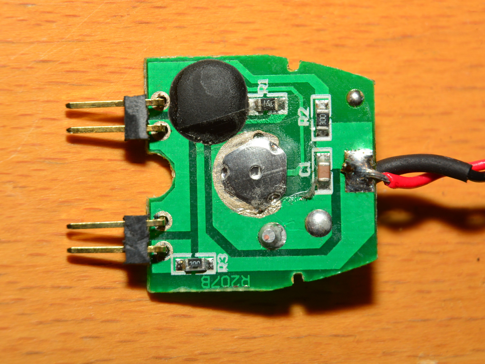 So, what I did was to get a sheap flashing LED bicycle light and strip it of it's plastic shell. This is what I found inside. Very neat. I replaced the original LEDs with pin terminals and solderd a 380 Ω resistor in series with the power wires (the original power suppy was two 3 volt button cells, so I guess 14.8 volt would break it). The only drawbacks is that it flashes a litte too fast and that it's initial state is off. You have to press the silvery clicky-thing in the middle twice to get it flashing.
A lightbulb is resitstive and hence works quite straight-forward. You apply voltage to it which produces a current through the filament and it shines. More voltage gives higher current and brighter light (until it breaks).
A LED on the other hand is a semiconductor and is not resistive, which messes things up a bit. A LED has a forward bias voltage. As long as the voltage over the LED is lower than the bias voltage, it will not shine at all and no current will flow through it. Once the voltage over the LED exceeds the bias voltage the LED will start to conduct. If voltage is increased further, something called the avalanche effect will come into action; The current will increase drastically and destroy the LED.
This effect is handled by connecting the LED in series with a resistor to limit the current. Smaller resistor will give higher current and brighter light. Bias voltage and maxial current is found in the datasheet for the LED. My LEDs have a forward bias voltage of about 3 volt and a operating current of 20 mA, so a 500 Ω resistor would be sufficient when connected to a 4S system (14.8 - 3 / 0.02 = 565).
Green LEDs are often brighter than red and white LEDs and brighter still than blue and orange LEDs. To make all LEDs have the same intensity the brightest ones can be dimmed by using larger resistors than the others.
Most high-power LEDs have a quite narrow beam, often around 20°. For navigation lights we want a broader beam. One way to make the LEDs spread their light more is to grind the surface of the plastic bulb with fine sandpaper. This creates a lot of microscopic scratches that refracts the light in different directions.