Maximum Period NLFSRs
Below we give a complete list of n-bit NLFSRs with the period 2n−1, n < 26, for the following types of feedback functions:
x0 ⊕ xa ⊕ xb ⊕ xc· xd
x0 ⊕ xa ⊕ xb· xc ⊕ xd· xe
x0 ⊕ xa ⊕ xb ⊕ xc ⊕ xd ⊕ xe· xf
x0 ⊕ xa ⊕ xb ⊕ xc · xd · xe
where "⊕" is an XOR (addition modulo 2) and " · " is an AND.
The maximum possible period for a n-bit NLFSR is 2n. The NLFSRs listed below do not include all-0 state in their longest cycle of states. They can be extended to have the period 2n by adding to their feedback function a product-term ¬x1 · ¬x2 · ... · ¬xn−1, where "¬" is a NOT. This increases the circuit complexity of feedback functions, which is undesirable for many applications. For this reason, we prefer to focus on NLFSRs with the period 2n−1.
The results given below were computed by a brute-force simulation which feasible for n < 26 only. FPGAs make possible finding larger
maximum period NLFSRs, as shown in this article.
INTRODUCTION TO NLFSRs
The general structure of an n-bit NLFSR is shown in Figure 1.
It consists of n binary storage elements, called bits or stages, and a feedback function f(x0,x1,...xn−1). For each i ∈ {0,1,...,n−1 }, the state variable xi represents the value of the bit i. At each clock cycle, the content of the register is shifted one bit right.
The value of the bit n−1 is updated according to the feedback function f.
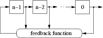
Figure 1: The general structure of an n-bit NLFSR.
The configuration shown in Figure 1 is usually referred to as the Fibonacci configuration. One can also represent an NLFSR in the Galois configuration, in which any stage has its own feedback function.
Figure 2 shows an example of a 4-bit NLFSR with the feedback function f = x0 ⊕ x1 ⊕ x2 ⊕ x1· x2.
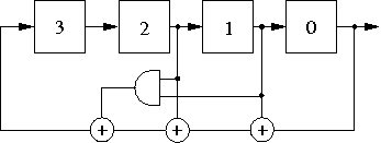
Figure 2: An example of a 4-bit NLFSR
FORMAT OF FEEDBACK FUNCTIONS
In the format we use in the list below, the function f = x0 ⊕ x1 ⊕ x2 ⊕ x1· x2 from the example in Figure 2 is represented as 0,1,2,(1,2). Indexes of variables of each product-term are separated by a comma. If a product-term has of more than one variable, we put round brackets around the indexes of its variables.
BASIC AND IMPLIED CASES
The state transition graph of an n-bit NLFSR is branchless, i.e. consists of pure cycles, if and only if its feedback function is of type
(1) f = x0 ⊕ g(x1,x2,...,xn−1)
where the function g(x1,x2,...,xn−1) does not depend on the variable x0.
Each NLFSR N with the feedback function of type (1) has a revserse, a complement, and a reverse-complement NLFSRs which generate sequences which are reverse, complement and reverse-complement of sequences generated by N, respectively. In the list below, we show only the basic case. Other three cases are not included.
FEEDBACK FUNCTIONS OF n-BIT NLFSRS WITH THE PERIOD 2n−1
- 4-bit NLFSRs
- 5-bit NLFSRs
- 6-bit NLFSRs
- 7-bit NLFSRs
- 8-bit NLFSRs
- 9-bit NLFSRs
- 10-bit NLFSRs
- 11-bit NLFSRs
- 12-bit NLFSRs
- 13-bit NLFSRs
- 14-bit NLFSRs
- 15-bit NLFSRs
- 16-bit NLFSRs
- 17-bit NLFSRs
- 18-bit NLFSRs
- 19-bit NLFSRs
- 20-bit NLFSRs
- 21-bit NLFSRs
- 22-bit NLFSRs
- 23-bit NLFSRs
- 24-bit NLFSRs
- 25-bit NLFSRs
REFERENCE
E. Dubrova, "A List of Maximum Period NLFSRs", Cryptology ePrint Archive, Report 2012/166, March 2012,
http://eprint.iacr.org/2012/204.
CONTACT PERSON
Elena Dubrova
School of Information and Communication Technology
Royal Institute of Technology (KTH)
Stockholm, Sweden
dubrova@kth.se