The third version of the SmartBadge builds on the lessons learned from the two earlier iterations which have been used in classes at KTH: Mobile Personal Communications module of the Telecommunications "finger" course during Spring 1997) and University of Wollongong (during Summer 1997).
See figures 1 and 2 of the article: Mark T. Smith, "SmartCards: Integrating for Portable Complexity", IEEE Computer, August 1998, pp. 110-112, and 115.
A preview of what this year's looks like (PDF).
The bare board before parts are mounted on it (2481K JPEG). It is a 10 layer printed circuit board with laser drilled holes.
The first badge was operational on 16 April 1998, with a program loaded via the TAP Master and setting a GPIO output.
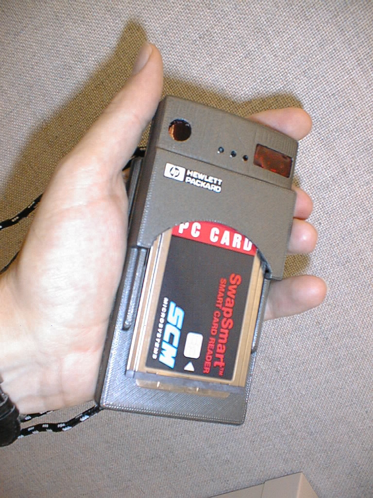
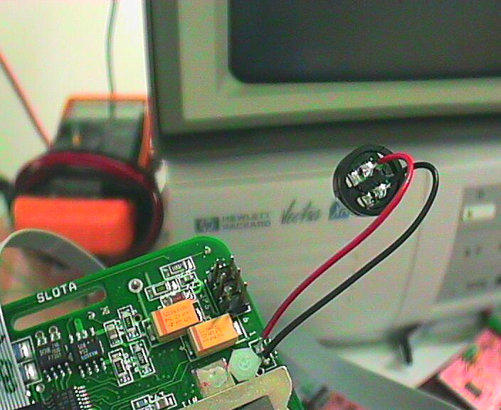
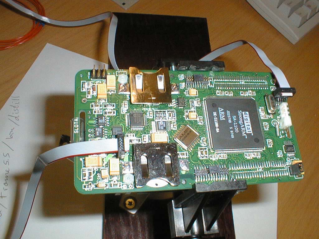
Scan of the first badge (running on a bench power supply - via the red and black wires) Front (370K TIFF image) and Back (372K TIFF image). Although this badge shows two 50 pin expansion connectors on the back (which were useful for testing the board), the connections are not attach (but can be) to the rest of the boards. The badge is 63 x 114 x 14 mm.
A view of the packaged badge ( 337K JPEG) as shown by HP at Comdex'98, November 16-20 1998.
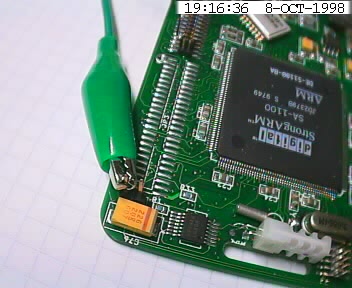
The basic system consists of a Intel (formerly Digital) StrongArm-1100 processor, sensors, some built-in communication links, and a PCMCIA interface.
A memory map for the badge shows where the Flash and SRAM are mapped as well as where each of the devices is mapped.
Some information about using this device to digitize sensor data is available from one of the groups.
As of 12 Aug 1998, the badge said it's first words: "Hello I am a Badge. Do you want to play with me?" This was done by Mat Hans of HP Labs who output synthesized speech in the form of a .wav files using a program running on the badge.
Alternative for the future: Fenwall Electronics +1 508 478-6000, NTC surface mount end band thermistors - 100 Ohms to 1Megohm, 2-10%, $0.35 to $0.15 for quantities 5,00 to 100,000 [5% resistance tolerance at 25 degrees C]
The SA-1100 has 28 general purpose I/O pins. These can be individually assigned as inputs or output. Many have alternate assignments (controlled by GPIO Alternate Function Register (GAFR)).
Buffering to allow both 5V and 3V PCMCIA cards to be used. The PCMCIA slot conforms to version 2.X of the standard, and can support 8 and 16 bit data transfers, except for DMA. The StrongARM cannot perform a PCMCIA DMA function or implement a 32 bit CardBus protocol.
Although the SA-1100 can read a bit to detect if a PCMCIA card is actually plugged into the socket (PSKT0CD~ ignal via the GP10 pin on the SA-1100), this interface does not at all support 'hot insertion' of PCMCIA cards. To do so would have very much complicated the design and occupied a lot of space. Therefore: One has to insert or eject PCMCIA cards with the power off, but this seems like a small thing for the badge. You don't need to remove the batteries; just pulling a jumper on JP6 is enough.
The setup instructions for the Badge3 board. With details of how to set the various jumpers and how to connect to the TAP Master for programming.
You will find in the bag with your badges another bag containing, parts which can (microphone and speaker) or must (certain jumpers) be added.
JTAG 1149.1 connector which can be used for both debug and for in circuit programming of the FLASH memory. Initial code load will be a a bootstap for the StrongARM to let it get the rest of its bits via the IRDA interface.
JTAG programming is done by a TAP Master card in a PC. The TAP programmer information(PDF).
A photo of the TAP master card showing the correct orientation of the cable that connects to the JTAG port on the badge. Note also that on the other end of the cable there is a spacer. It isn't visible in this picture, but it is visible in Figure 5 of the Badge3 Setup Guide (see document noted above). It's needed to make the cable connector clear the crystal on the badge. Leave it attached to the cable, not the badge.
To connect a speaker and mic to a badge use one of the small microphone units (that we used with the original badges), be sure to observe the polarity. The case of the microphone (you can see a small trace from one of the connection points on the mic going to the case) needs to be connected to pin 2 of the mic connector on the badge. Pin 2 is indentified as the round pad. Microphone picture (51KB)
Likewise, connect the black wire of the small speaker to pin 2 of the speaker connector on the badge (also round). Although the speaker probably doesn't care about polarity the microphone does. Speaker picture (67KB)
The current badge is missing a "removal contact", so that you could know if the badge has been removed and thus de-authenticate it.
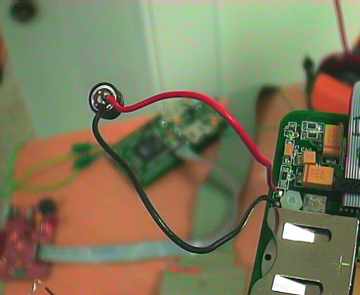
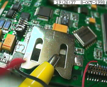
The badge may be powered by using an external supply attached via the battery jumpers as shown - note the orientation of the strips on the connectors. The strips may be of any color, but they should have the same orientation.
The external power supply is connected to the other end of the ribbon cable. Note the orientation of the color strip on this end.
You need create a plug to put into jumper JP7 which connects pins 1,2,3,and 4. An example of such a jumper made with a connector and wire looped around the relevant pins.
Note that if you have inserted such a header you can power the board from an external supply by connecting to the battey holder's positive electrode and to the ground of the reset pins.
It is possible to both power the badge and provide one or two serial interfaces using a new serial+power board.
The serial+power board needs modifications to the RS-232 modules to use them with ANGEL. Angel wants to talk to the ARM debugger over UART3. The PDF file shows a simple mod to make it into UART3, as it should have been. UART1 still comes out as well.
When running the ARM tools from a notebook, you need to set the serial driver to "Flow control: NONE" and uncheck the box to disable the 16550 FIFO. You will find all these controls under the "Control Panel", "System", "Hardware devices", "COM1", "Port", and "Advanced".
IEEE P1451 is a standard for Standard for Smart Transducer Interface for Sensors and Actuators. A nice introduction to smart sensors is "Smart Sensors" by Mark Clarkson and "Smart Sensor Networks of the Future" by Jay Warrior.
directio.zip is freeware that Andreas Schmidt found. It contains lots of stuff, but the point of it all is a single file called GIVEIO.SYS. This is a device driver for NT 4.0 that when called will give an application permission to successfully execute I/O instructions. I/O instructions are trapped under NT 4, and so this device driver is needed to set permission masks properly. None of the tap master code will run without it.
instdrv.zip is freeware that Mark Smith uploaded from the net. It is referred to in the directio.zip README.TXT file. It's a handy transient device driver utility that will load and start a device driver without having to permanently install it, or having to reboot the system after it has been installed. It's fine for installing GIVEIO.SYS. Alternatively, you can use the control panel and the devices program in NT version 4 to install GIVEIO.SYS the NT way. If you go this route, you can dispense with instdrv.
tap.zip - contains Mark Smith's collection of TAP master code to date. Primative, but it works. Currently it only runs under NT version 4 and was compiled using Microsoft Visual C++ version 5.0. If you are really desparate, it compiles under MS-DOS using Microsoft C version 6. Sources and executables are in there. [Copies of the this file are available to our collaborators.] Here's what you get:
| TAPLIB.C | This is a library of TAP master hardware level routines. Really low level, and takes care of all the needs of the TI 74LVT8980 controller chip. |
| TAPLIB.OBJ | typically linked into everything. |
| ARMPIT.C | This is a library of ARM JTAG level routines. They handle all the dependencies of the ARM JTAG scan chain, data and instructions. |
| ARMPIT.OBJ | typically linked into everything. |
| LOOPIT.C | This is a loopback check program to verify that the tap master board is working properly. It generates random 280 bit scan chains and loops them around, verifying as it goes. It doesn't need a target device like the badge to do this, as it internally loops back. If you suspect there is something wrong with your tap master board, this will let you know. |
| RESET.C | A simple appliation that resets the tap master board. Don't really need it, but there it is. |
| GETID.C | This application will read and display the ID number encoded inside the StrongARM chip. It's a handy way to see that everything is hooked up properly. Get everything connected, apply power to the badge and run this program. For these badges, you should see back the result 0x9108406b. The '9' is the silicon rev, so it can be different, but the other numbers cannot. If you don't see this pattern, then something is wrong. |
| ERASEFL.C | This will erase the entire flash (including the flash bootblock from addresses 0x00000000 to 0x00001fff (the lowest 8K bytes of the FLASH). [PC executable is erasefl.exe] |
| LOADFL.C | This will load an object file from the ARM tools into FLASH. It expects that the object file will have been linked with the -bin -aif options, resulting in a flat code image preceeded by an AIF header. It gets the starting address and code length out of the header, and then loads it into FLASH. Having data mixed in with instructions is OK, but it can't deal with multiple object blocks with separate load addresses in the same object file. This won't happen if you use the -bin -aif options with the ARM linker. You can load anywhere in flash, not just the boot block, but at this time the boot block is probably the most useful place to load. The latest version supports better internal FLASH status reporting. [PC executable is loadfl.exe] |
| DUMPFL.C | This allows you to look at what is in flash, it takes two arguments - the first is the starting address in HEX and the second is the length in decimal to be dumped. The flash is a 16 bit wide device, so it spits out data in 16 bit chunks. It's fun to use it to see that the flash has really been erased, and that your code actually made it in. You can look anywhere in the 1MB of flash, not just the boot block. Don't try looking into SRAM. That isn't supported yet. [PC executable is dumpfl.exe, example use "dumpfl 2000 16"] |
That's what we have so far. All of these programs are run from a Command Prompt window under NT4. There are no fancy GUIs here, and the code is admittedly primative, but it should get you off the ground. It can be improved/added to as we need.
As of 99.01.06 there is a new TAPMASTER document and new routines.
This section is based on Peter Beadle's e-mail of 98.06.02, summarizing what he did when he visited here.
The setting and flags for use when compiling a program under the ARM Tools for use on a SmartBadge running Angel are available as a PDF file. {New as of 99.03.26}
This then compiles and links the executable and leaves it in g:\badge3\stockholm\debug\stockholm.axf
The axf file can then be loaded into the badge with the flash loader.
You can also examine it in the project manager by double clicking on the arm executable image entry in the project manager window, then debug, then object and finally stockholm.axf This will disassemble the image and show you the sysmbol table etc.
Use the follwoing command lines:
armcc -Ospace -gxo  -g+ -apcs /nofp/noswst -cpu StrongARM1
-D__TARGET_CPU_StrongARM1 -D__TARGET_FEATURE_HALFWORD -D__TARGET_ARCH_4
-D__APCS_NOFP -D__TARGET_FEATURE_MULTIPLY -D__APCS_NOSWST -fc  -o
G:\badge3\stockholm\Debug\mini.o -c -MD- G:\badge3\stockholm\mini.c

armasm -apcs /nofp -PD "ROM_AT_ADDRESS_ZERO SETL {TRUE}" -liston -xref -apcs
/noswst -cpu StrongARM1 -o G:\badge3\stockholm\Debug\init.o -MD-
G:\badge3\stockholm\init.s

armlink -info total -remove -entry 0 -map -libpath
c:\arm211\lib\embedded\armlib_cn.32l -rw-base 0x08000000 -first init.o(Init)
-aif -bin -nozeropad -o G:\badge3\stockholm\Debug\stockholm.axf
G:\badge3\stockholm\Debug\init.o G:\badge3\stockholm\Debug\mini.o
Echo program echo.zip
The Olicom GoCard 2220 Ethernet PC Card is PCMCIA ethernet card which has 64 Kbytes buffer memory and 128 Kbytes flash memory for Card Information Structure (CIS). It uses the Intel 82595TX ISA/PCMCIA High Integration Ethernet Controller. It is 86.5 x 54.0 x 5.0 mm in size and uses 0.75 Watt in 10Base-T operation and 50 mWatt in power save mode.
Attribute Memory consists of: