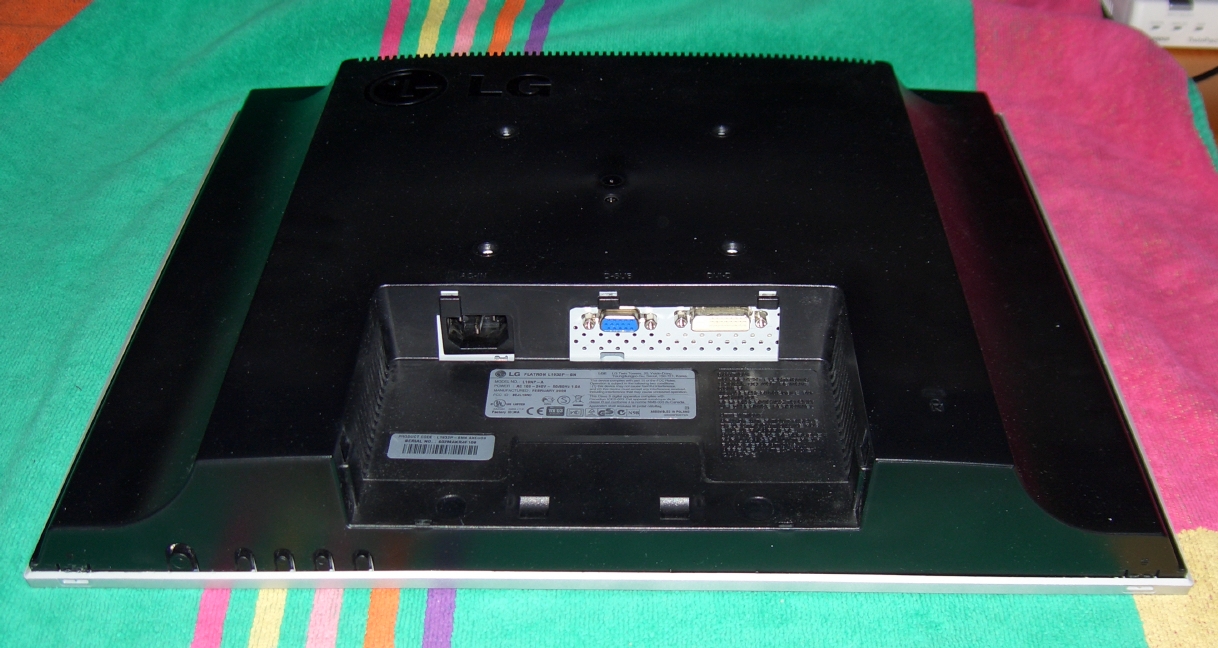
LG Flatron L1932P repair
In mid-August 2009 my LG Flatron L1932P display failed, the appearance was that the
display would turn on for a few seconds, then the screen would go dark. The
description below shows how to remove the power supply (mains to DC converter)
in order to replace the capacitor that has failed.
This page attempts to describes what I did, but only for informational
purposes. It is only for use by those know how to repair power supplies.
- The zeroth step was to disconnect all the external cables from the
display. This includes the mains power -- for those who missed the
all cables part of the previous sentence.
- The first step was to remove the four screws attaching the display to the pedestal.
- The next step was put a beach towel on the table and put the display
face down on it.
- Next remove the screw holding the back of the case to the power
supply/logic case (you can see it in the center of the space between the four screws that were used
to attach the pedestal.
- At this point it is time to remove the bezel from the monitor. Note that
you have push in the plastic catches - as shown in the figure. You will need
a sharp blade to go around the back of bezel to carefully push in the small
ridge that holds the bezel on.
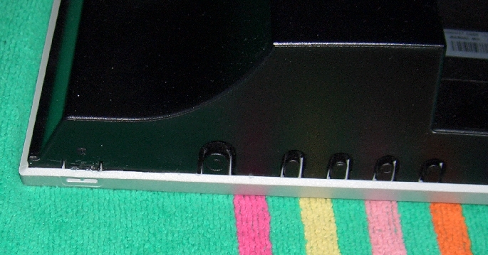 . Notice that there is one plastic catch located near the power supply
button on the lower lefthand corner (shown in the figure) and another on the lower right hand corner.
. Notice that there is one plastic catch located near the power supply
button on the lower lefthand corner (shown in the figure) and another on the lower right hand corner.
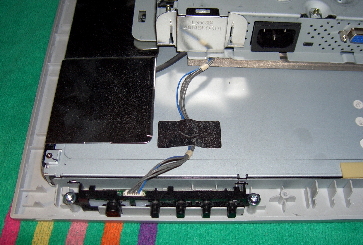
- Removing the back reveals the power and other control buttons on a small
circuit board attached via a cable to the power supply. You can remove this
button module by unscrewing the two screws, that hold it in place.
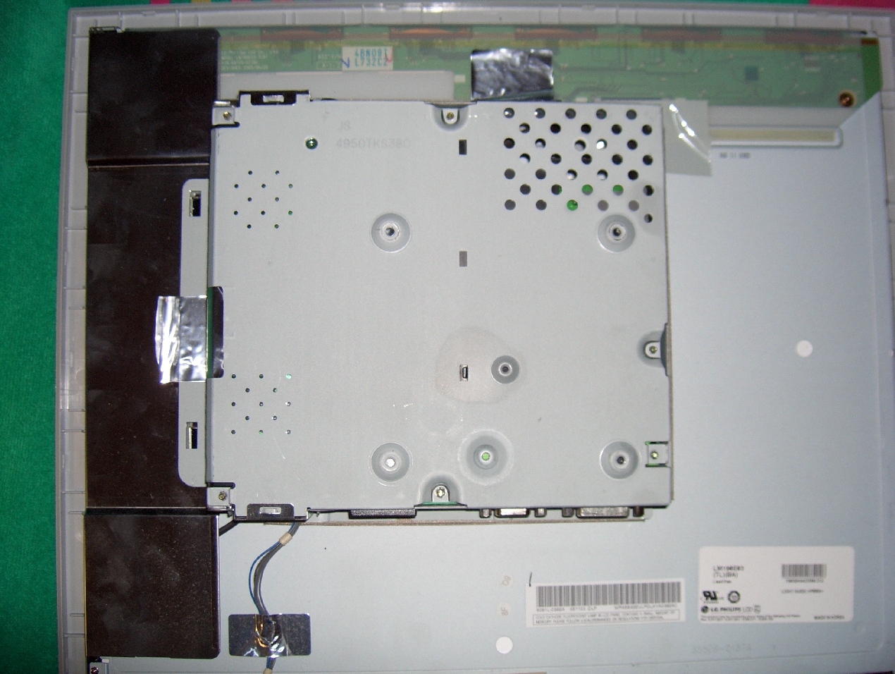
- The power supply is mounted on the back of the LCD panel.
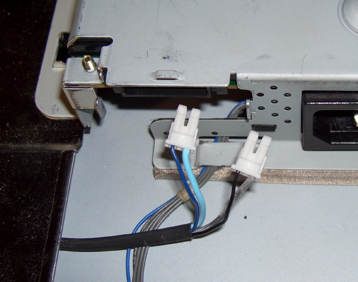
- The next step is to remove the shiny metal cover from the corner of the
power supply, this gives you access to the power connection to the backlight.
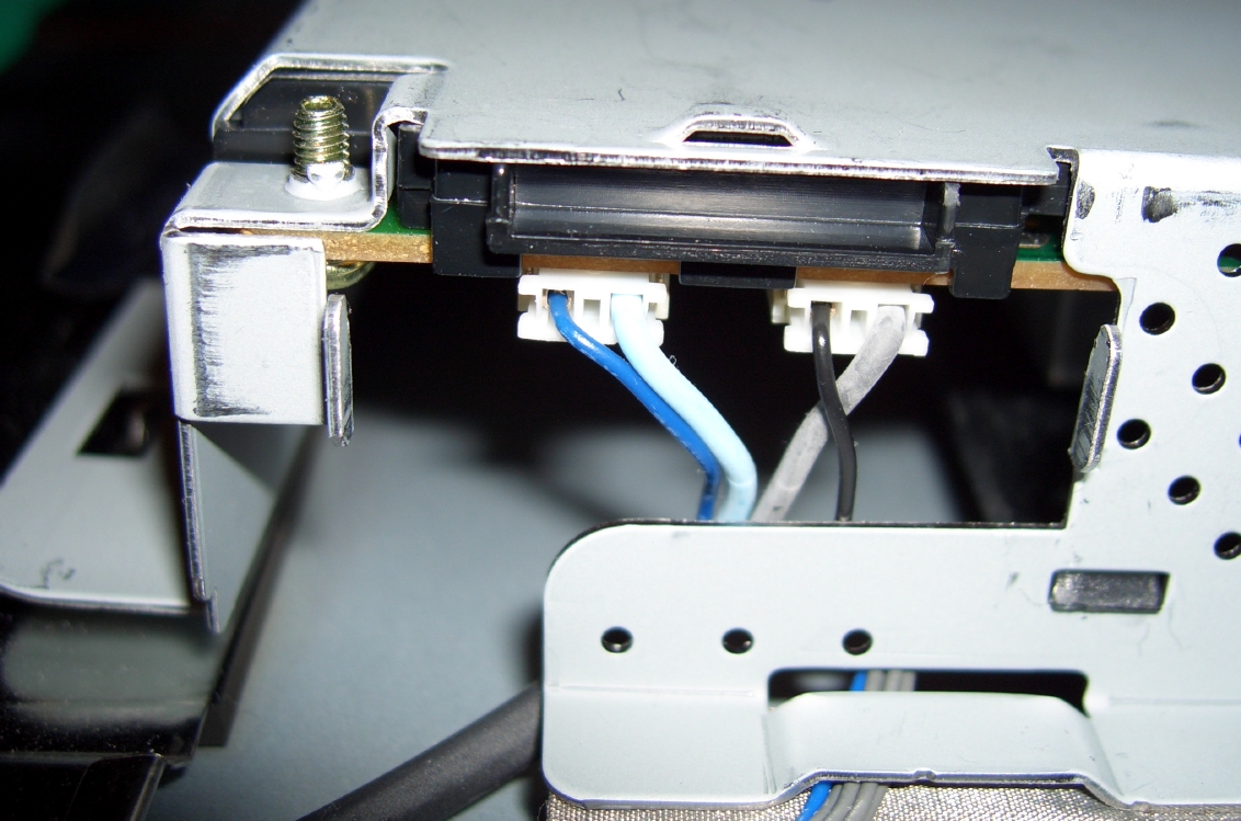
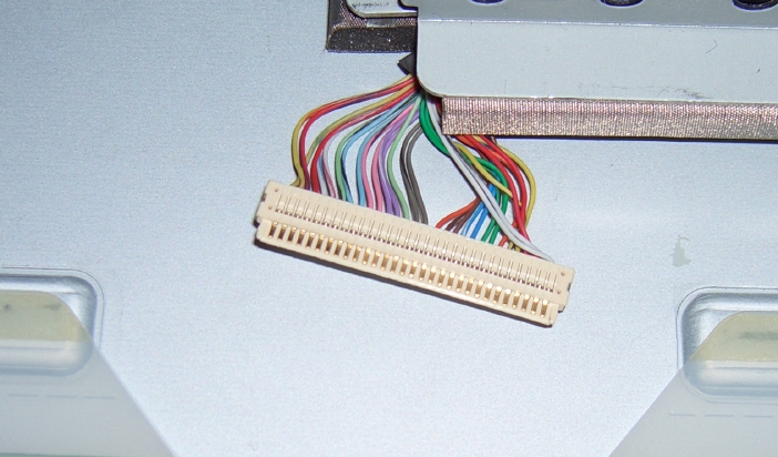
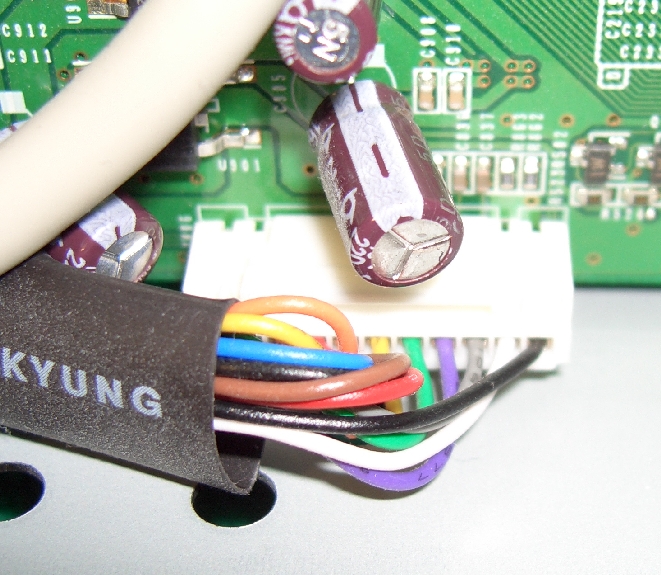
- The image below shows the connectors on the cable to the backlight.
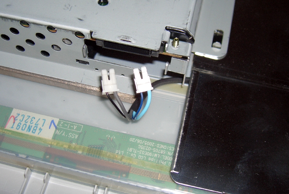
- There is a similar shiny metal cover at the top of the power supply. Note
that the cables are in the mirror arrangement (i.e., the cable with the two
blue wires is to the outside of the power supply case in both cases, while
the conenctor with the gray and black cable is to the inside in both cases.)
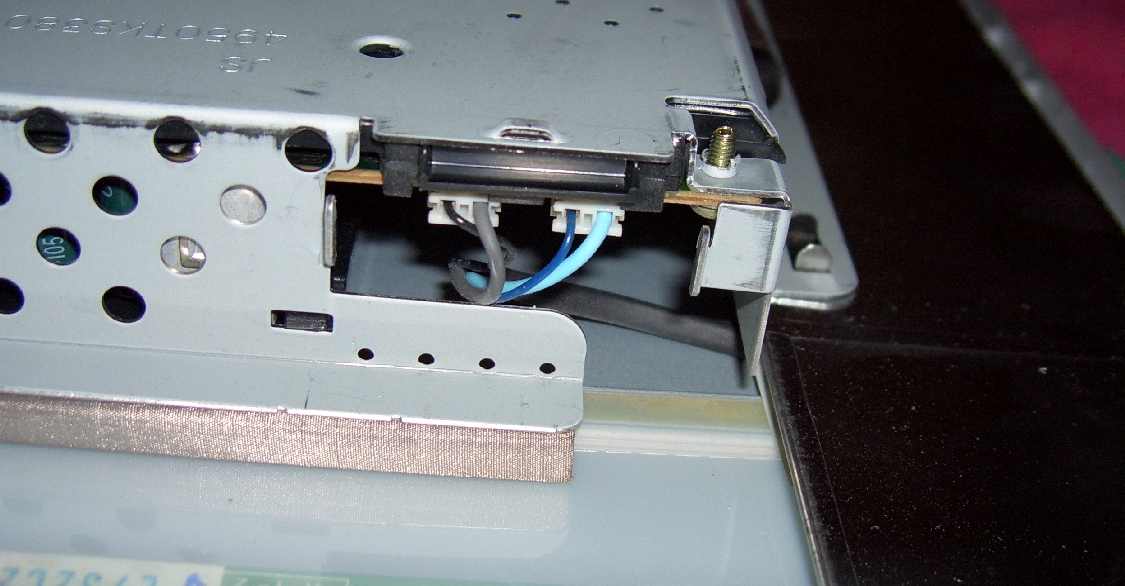
- Detailed view of the connectors on the cables to the backlight from the top
of the power supply case.
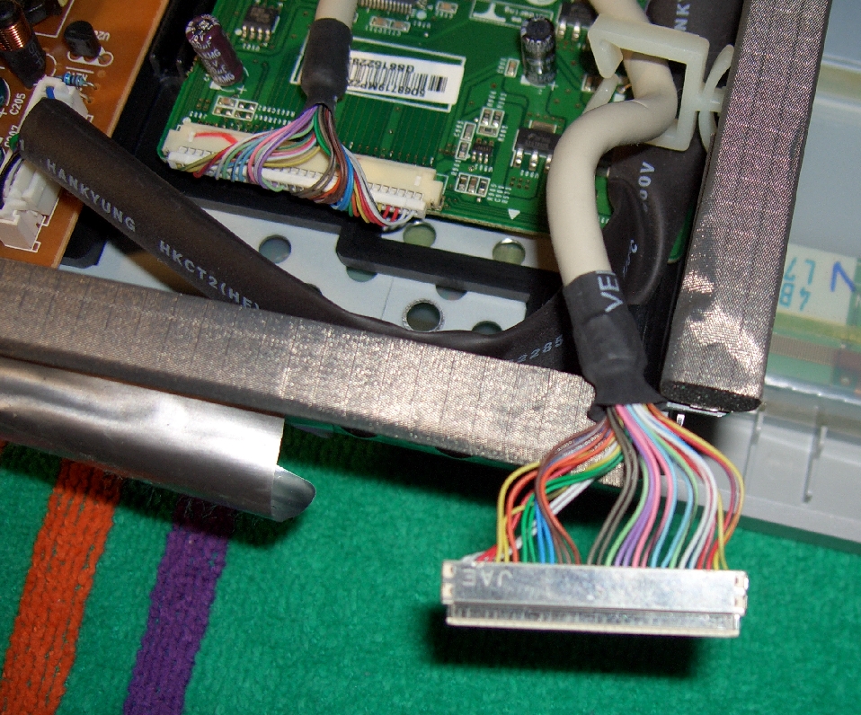
- Next remove the tape from over the cable from logic in the power
supply case to LCD panel. Note how the cable exists the power supply/logic case.
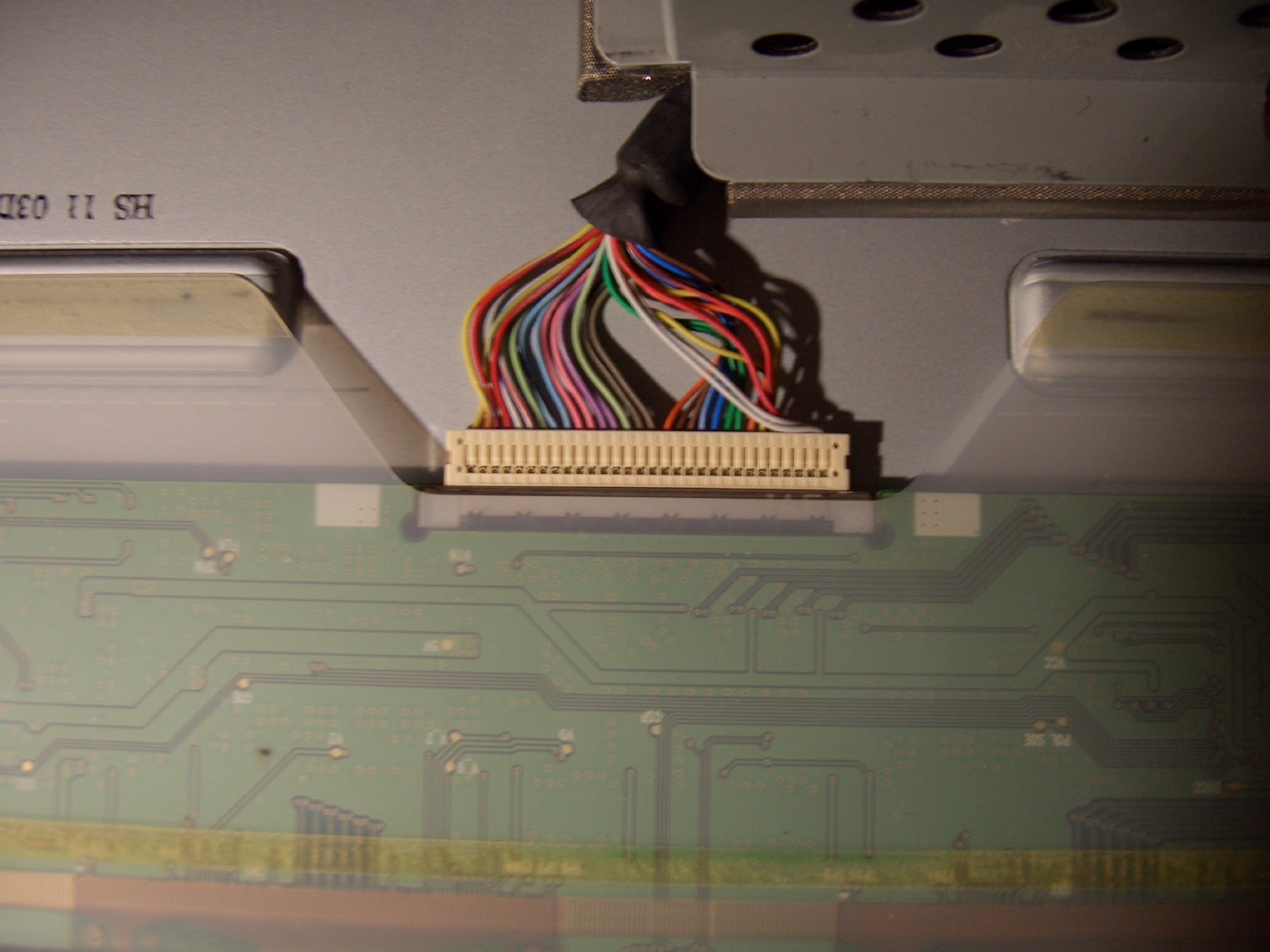
- The image belows shows the logic cable to the panel, after bing removed
from the connector.
- With all the cables now removed, remove the tape at the side of the
powersupply and logic module and turn the module towards you, it will look
like this:
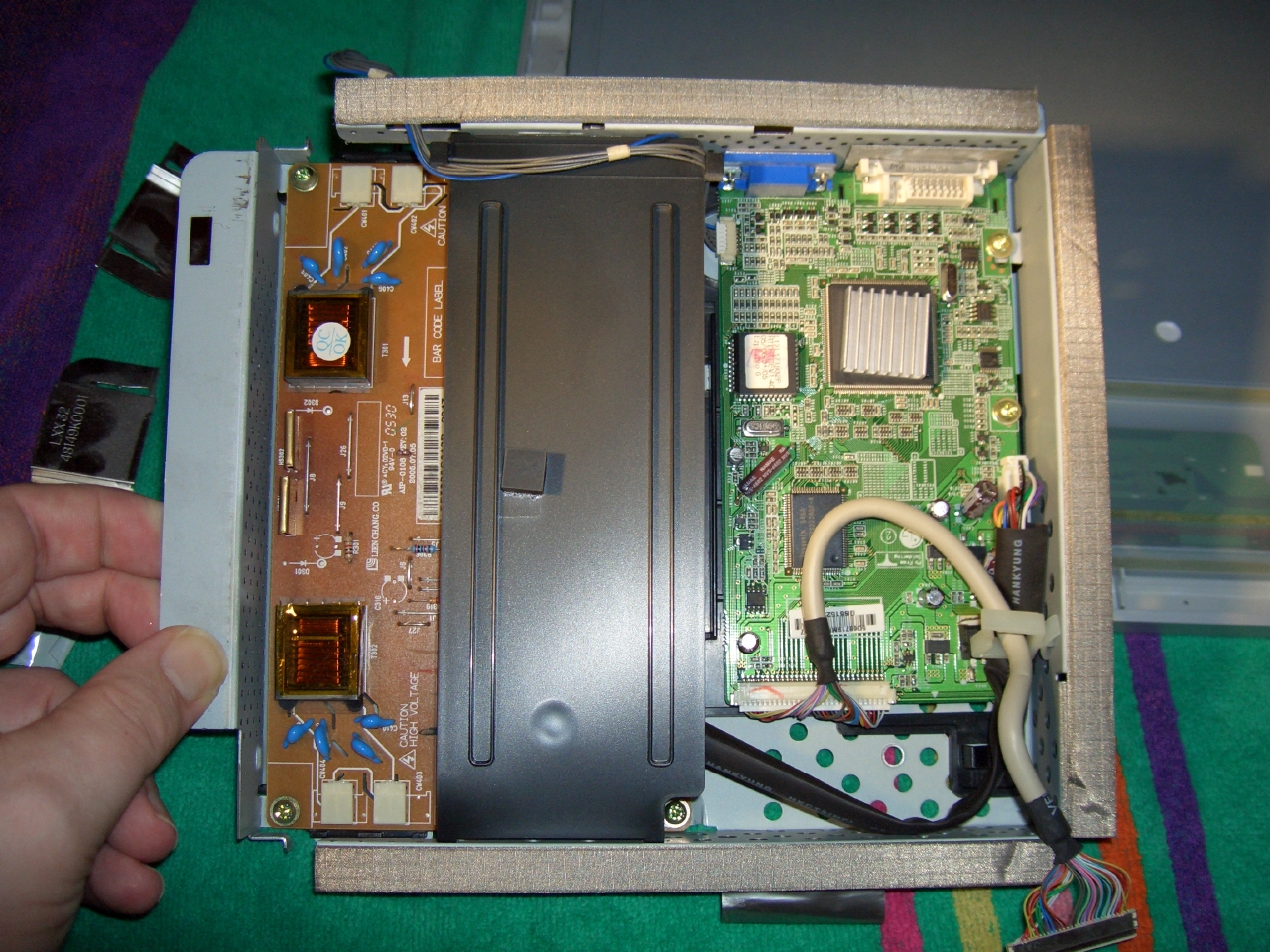
- With the module in this position we can see the underside of the connector
on the cable to the panel.
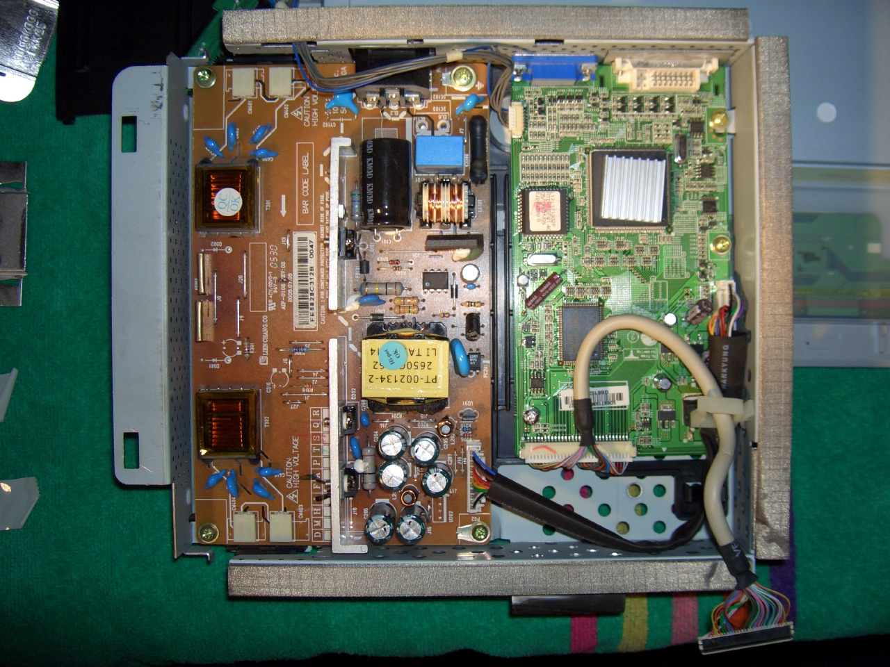
- Removing the black plastic cover reveals the mains to DC converter.
- An alternative view of the logic module from above showing the mains supply
to DC converter in the middle. Note the four screws holding the power supply
(mains to DC converter) into the chassis. You will have to remove these
screws to remove this module. Before removing this module we will take a
look at the suspect capacitor in the DC converter and the cables that can be
removed to make it easy to remove this module.
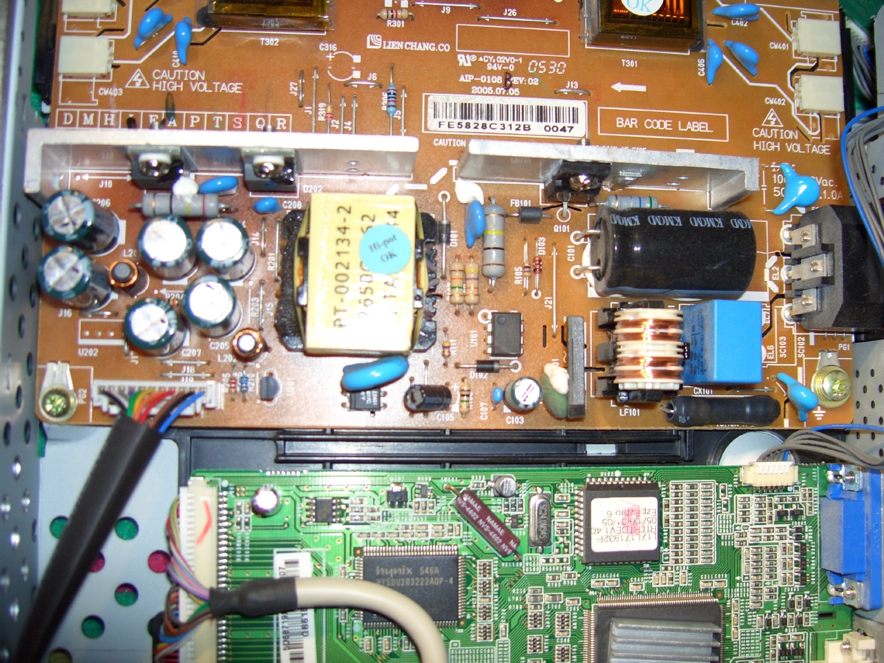
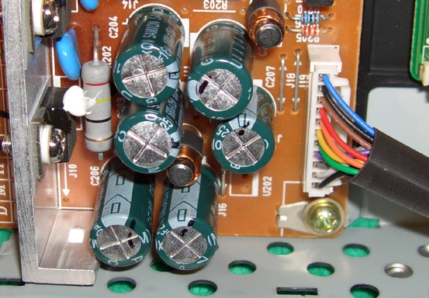
- Closeup of view of capacitors of the DC converter. Note the slight bulge in
the capacitor in the middle of the picture.
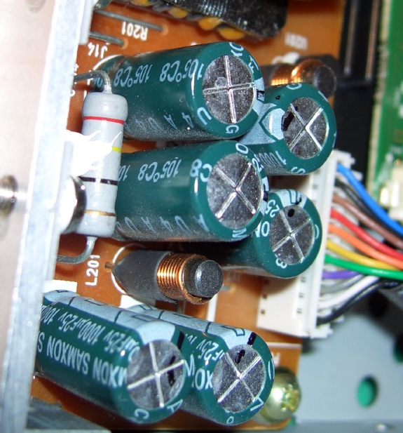
- When view from the side we can see that this capacitor is sticking up a bit
higher than the capacitor above it (C204). It is also possible to see the
vent split apart a little.
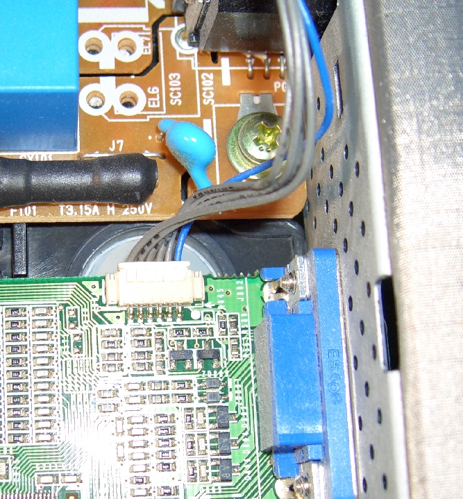
- Take a close look at the connector for power to logic board - so that you
will be able to put this cable back into the connector properly when
reassembling the unit.
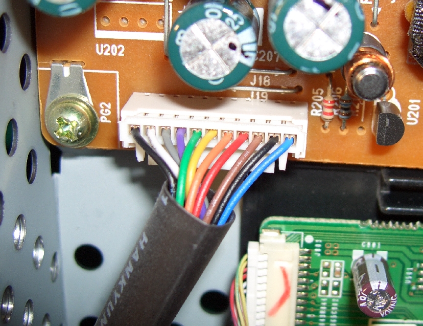
- The other end of the power cable to the logic board connects as shown
below. You do not need to remove this cable to remove the DC converter.
- Note also the connector on the logic board running to the button module.
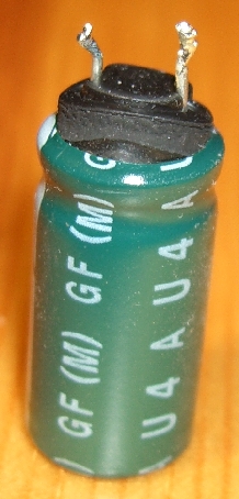
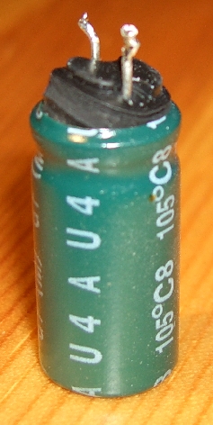
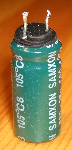
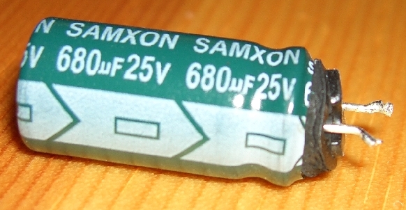
The failed capacitor was a 680 microFarad (680µF) 25V capacitor. After desoldering it from
the board, it was clear why it was sticking up higher than the equal height
capacitor beside it, the plastic seal was being pushed out past the crimped
end by internal pressure. I replaced this capacitor with a new
Nichicon Aluminum
Electrolytic capacitor HE Series (UHE1E681MPD) rated at 7000 Hrs @ 105°C. Such a capacitor is
available as (Digikey part number 493-1554-ND).
Their catelog price on 19 August 2009 was 0.66 each (or 10 for $4.83).
Note when inserting the replacement capacitor to align the polarity just as
the capacitor that you are replacing. An advantage of taking
pictures of the circuit board before attempting any repair is that you can go
back to see how the original part was oriented.
In addition to this the other capacitors in this section are:
two 1000UF 25V, 470UF 25V, two 1000UF 16V. However, they did not need to be replaced.
After replair, the circuit board was replaced by reversing the order of the
steps above. The monitor works once again.
Some pictures of the bad capacitor.
Detta är en personlig hemsida och åsikter framförda
här eller i tillhandahållna länkar representerar
inte KTH.
This is a personal homepage. Opinions expressed here or implied by links
provided, do not represent the official views of KTH.
For information contact maguire@it.kth.se
Latest update 5 October 2009
© 2009 G. Q. Maguire Jr., KTH/ICT